Why?!
WHY did I not post the Arduino code to this page?!
It appears to have gotten lost when backing up my hard drive and switching distros. Oh well. It’s not like it was that impressive or hard to duplicate…if you know what you’re doing…which I don’t.
Replacement 8mm projector bulb from super bright LED and old cellphone charger.
One of my other hobbies is small-format film. Showing them, making them, etc. By small-format, I mean 8mm, Super 8, and 16mm movie film.
It started with a $25 8mm projector from a flea market and grew into a small of obsession from there. I bought a few cameras and some films off of Ebay. I had some fun one Halloween showing a bunch of horror shorts to some friends.
One of my better finds was this 8mm-super 8 projector. That’s right. It plays both 8mm *and* super 8 film! If you don’t know the difference, I invite you to skim through [this Wikipedia page.](https://en.wikipedia.org/wiki/8mm_film)
I don’t think there’s anything “magical” about watching something on real film. I find it somewhat comforting that my brain is being tricked by having successive images reflected into my eyes at 16 frames per second and *that’s it*. That’s as far as the illusion goes. It is literally one image coming right after another. Don’t get me wrong. LCD screens and even CRTs are fucking cool. But film is simple and almost primordial. And what illusion there is is fragile. If the film gets jammed it will burn a hole in the frame. Learning to switch reels is a dance considerably more athletic than learning a new UI. It’s like being an auto mechanic, but instead of just fixing cars, you’re presenting a work of art.
And, yes. “I was a Teenage Frankenstein” is art. I don’t care what you say.
Unfortunately, these old projectors use incandescent bulbs that get *really* hot and occasionally explode. That’s what happened to this poor guy. What’s worse is that nobody makes these bulbs any more. You can find them for sale, but they are pretty damn expensive and in very limited supply. So, in my attempt to keep film alive, I bought [this fella](https://www.jameco.com/webapp/wcs/stores/servlet/Product_10001_null_2096851_-1) from Jameco Electronics and opened up an old cellphone charger. This is what happened:
You might notice that this LED comes attached to it’s own heat sink. Regardless of the voltage applied, this thing generates enough heat to burn itself out. It’s a good thing the projector has a built-in fan to keep that old monster of a bulb cooled down.
A couple cool things about cellphone chargers: they usually take in 110-120VAC and put out 3-5VDC (perfect for this LED) and they use [PWM](https://en.wikipedia.org/wiki/Pulse-width_modulation), which makes them really small and light.
Luckily the operating voltage for the projector bulb is 120VAC, so I won’t need to do any modifications. All I have to do now is fit a square peg into a round hole.
Basically, I just need to make a nice case for this so it doesn’t hit anything conductive and short out. Those two squares of solder on the bottom left of the circuit board are the AC in, so I need to get . Pretty soon this is going to be a pretty satisfying hack!
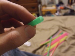
How to make a Buckyball out of Bendy-Straws
At first I tried making a buckyball out of toothpicks and glue, but it kept falling apart and was taking a very long time. I did a search, and it looks like most people either make them out of either candy and toothpicks or paper. Well, I didn’t want ants to start eating my buckyball and the origami method looked a little boring. So I tried this.
Materials:
at least 240 bendy-straws of the same size
a roll of scotch tape
Step 1: Acquire straws and tape
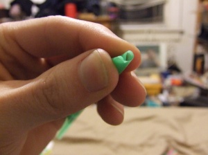
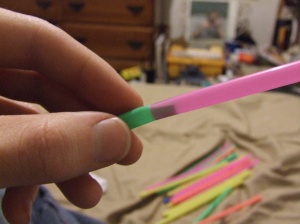
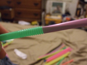
Step 2: Make a triangles out of sets of three straws. Connect two straws by bending one end inward and fitting it in to the end of another straw. Connect the short end of a straw to the long end of another or vise-versa. If you connect a short end to a short end, you’ll end up with an acute triangle. We want all equilaterals. Make a whole bunch of triangles until you run out of straws.
Step 3: Make pyramids. Take 4 of your triangles and tape them together to form a pyramid. Do this over and over until you run out of triangles.
Step 4: Tape the pyramids together. If you did everything right, you should be able to fit 5 pyramids together into a shape that looks like a cross between a UFO and a Mercedes logo. After that, you can either make one more pentagon-shaped thing, or just continue taping pyramids to your existing shape. You’re probably beginning to see how these fit together.
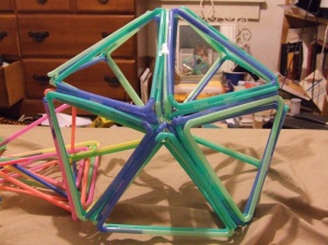
Step 5: Finish up! Just tape all your pyramids together and you should end up with a dodecahedron like this.
The cool thing about this is that it’s pretty much infinitely expandable. You could make more pyramids and build on to it or you could make more buckyballs and tape those together. I haven’t done this, but at a certain point I’m sure I would switch to duct tape or zip-ties.
New Diodes, New Ideas. New Hackerspace?
After much frustrated testing, it turned out that my one measly $2 diode from Hong Kong was a piece of $#!T. Surprise, surprise.
So, I ordered a couple more. A couple more. I received three. Don’t know why. Don’t know if I paid for it, but I’m not complaining either way. All three appear to be in working condition, but have not been tested (on account of the lack of safety equipment.
I have also received a new diode driver which I’m going to try very hard not to burn out this time around. It seems better suited for the project anyway. Pictures coming soon.
Since I had some trouble with X-axis wobble, I think I’ll try something new. The carrier for the laser is a small piece of wood with a hole cut in it. The carrier runs along the rail through that hole. My plan is to have two rails, and two holes in the carrier which will be lined with brass tubing to prevent friction. If they had steel tubing in the right size at the hardware store, I would have gotten it. Ç’est la vie.
I believe that the two rails in combination with the drive belt will create a sort of stable triangle, preventing the carrier from moving too much. And if it does move, I’ll rig something up with a spring and some bearings.
Despite this winter being “unusually” warm, it’s still not fun working in an unheated basement at those temperatures. Now that it’s warmed up a bit, I’ll be down there more often.
And boy, will I be getting stuff done! There’s a new hackerspace in town…probably. There is definitely an interested group of people, and we are working on securing a physical space. We are also working on securing a name. I think we are leaning toward “R00T Cellar”. Expect to hear more soon.
Progress has been made
Here are some things I’ve done in the past couple of months.
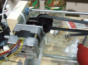 First, I decided that 1 1/2″ birch was to narrow and the machine wouldn’t go very far before it crashed and fell over or something. So I replaced it with 3″ poplar.
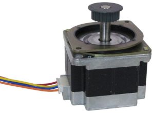
Most notably, however, I have replaced the old linear actuator system on the x-axis with this stepper and belt from an old scanner I found in the alley. I didn’t really want to do it at first because it’s a unipolar motor (6 wires) as opposed to a bipolar motor (4 wires) like the old motor. A unipolar motor can be turned into a bipolar motor simply by not using the two COMMON wires. I thought it would be a pain in the ass to find the Common wires as well as find the coil wires and group everything together correctly. Then I realized the Common wires were both Brown. So that was easy.
And as a bonus, the motor came with its own mounting bracket!
 Here’s the other side of the belt-drive. Once again, it conveniently came with its own bracket and pulley.
That 3/16″ steel rod you see in the back will either be replaced by a 3/8″ aluminum rod in the future or have a partner right below it to stabilize the carriage.
Notice how far apart the y-axis bearings are. I expect this to be much more stable.
 This is how the belt is fastened for right now. It will have to be temporary. It’s way to heavy. I will also need a belt tensioner. I’m working on some ideas for that.
Belt tensioners on Thingiverse:
http://www.thingiverse.com/thing:10274
http://www.thingiverse.com/thing:10082
http://www.thingiverse.com/thing:12733
That’s it for now. I have to go to work.
I’m back
Seems like it’s been a really long time, but it’s only been a couple of months since my last post.
So let’s get up to speed:
I ordered two laser diodes but only one came in. I didn’t take the initiative to contact the seller/s because they appear to be a gigantic factory in China and they’re dirt cheap. So I’ll just order another one if/when I need it. I’d like to get a box of several spares but I don’t know if that will be possible unless I land on some disposable income.
I took the old diode out of the Aixiz module (The process involved a hammer. It wasn’t pretty) and put the new 808nm 300mW diode in, which was a little tricky. I had to use a vice and a piece of wood with a hole drilled in it to protect the pins.
The diode is an open-can model, unlike the old one. This requires a little more care. Can’t allow dust and debris to get in there.
At the moment, I don’t have a good way of testing the diode. The beam is not visible to the naked eye and I don’t even have appropriate safety glasses yet. It also seems that none of the leads are connected by conductive material. I’ve tested it with the ohmmeter and I don’t get a response. I don’t think this means the diode is broken, but it seems odd to me.
I need a driver. The laser has an operating voltage of 2.2V and is rated at 300mW. That means it needs about 2.2V at 136.36mA. The last time I tried to make a driver it didn’t work. Perfboard is not my friend.
In other news, I have decided to replace the x-axis linear actuator system with a much lighter belt-drive system. I will have pictures in the next post.
Replacement Parts
At the suggestion of some very helpful redditors, I just ordered a couple of new laser diodes. (one for back-up) This time it’s an IR diode. 808nm, 300mW. The blu-ray diode was (bless her heart) 405nm, 100mW. In other words, the new one will have three times the cutting power but I won’t be able to see it without a camera. I have a feeling safety is going to be an issue.
Also , the new diodes are insanely cheap!
I bought a new multimeter from Radio Shack for about $20. You’d expect them to have the courtesy to include batteries for twenty bucks, but they didn’t. They take AAAs too. I hate AAAs I have a ton of AAs and 9Vs. What’s the point anyway? Why should there be two different sizes for what is essentially the same thing? I believe the sole purpose of the difference between AA and AAA is to piss people off.
Anyway, once I find some AAAs around here, I’m sure the new multimeter will do fine.
Tomorrow, I need to look into a new current regulator. I’d do it right now, but it’s about 1:30am and I have class in the morning.
Successful Failure
That’s what this blog should be called.
So, I got it up and running…for a while anyway.
Riding along the 3/8″ threaded rod and 1/16″ steel bar is the laser carrier. Made of good ol’ 1 1/2″ birch with a hole drilled through it and a 3/8″ nut inside, it has room for improvement. When cutting a piece of electrical tape, it wobbles quite noticeably, resulting in a kind of zigzag cut. I think I need to go to the hardware store this weekend and get another 1/16″ metal bar to stick on there, taking advantage of the stability of a triangle.
The Y-axis on the other hand, moves straight as an arrow…that is, when the bearings don’t fall of the tracks and the motor shaft doesn’t slide around in the rubber-hose-motor-coupler. zip-ties don’t seem to do the trick for that one.
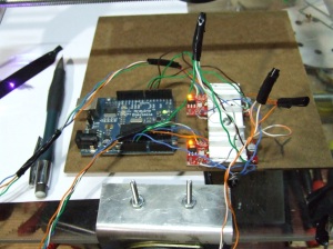 Running the show is the Arduino Diecemila hooked up to two EasyDriver version 4.4 stepper motor drivers from Spark Fun Electronics. As reported by other users, the A3967 get’s considerably hot, so I screwed on a heat-sink from a…stereo, I think. There’s a computer fan sitting on top of it now.
The wiring is like so:
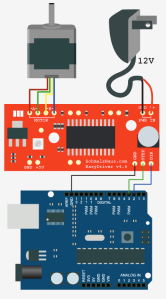 …except I’m using 8.4V instead of 12. It seems to work fine.
I can’t remember where I got this image, but it’s not mine. If it’s yours just let me know and I’ll give you credit. Since you’re using open-source hardware, I get this eerie feeling that you don’t care, but I’m in no position to make assumptions…In any case it’s a very nice image. Good job.
If you plan on getting some of those motors from All Electronics, the wire configuration is:
A1: Red
A2: Yellow
B3: Blue
B4: Orange
I got some basic code to work and the motors move fine. I still have a TON of software stuff to work out. I need something that will interpret GCode into Arduino and make it do everything it’s suppose to. I also need something to convert images into GCode.
Image==>GCode==>Arduino. That’s how this needs to work.
Anyway, all that would be fine if it weren’t for the fact that my current regulator quit on me, consequently burning out my laser diode. Quite depressing. I also need to get a new multimeter (not from Wally-World this time) because it seems to think 12V is around 43V. I thought it was the power supply for a while, and then I tested another 12V supply. It also read 43V. Verdict: cheap and shitty multimeter is cheap and shitty.
Ugh…doing some shopping this weekend.
I forgot to mention…
I got the motors (Minebea # 23KM-K217-P2V) from allelectronics.com for $12 each. It’s a great website. I highly recommend it.
Also, about that giant red stain on my workbench…I know it looks bad, but I promise I still have most of my digits.
REMINDER: Always wear safety glasses. Can’t let the blood spray into your eyes or you’ll go blind and you won’t be able to find the first aid kit.
…okay, it’s just wood stain from another project.


